- Vulkan Ray Tracing Acceleration Structure
…
加速结构(AS)通过空间层次组织场景,减少射线求交测试。Vulkan 将其分为两层:BLAS 组织几何,TLAS 组织实例。
示例使用 Vulkan-Hpp,省略初始化和错误检查。
createBuffer()、destroyBuffer()、submitAndWait()为应用封装;buffer 封装负责分配、绑定和对齐,提供.buffer与.address。使用 C++20 designated initializer,按成员声明顺序初始化。首次包含 Vulkan-Hpp 前关闭构造函数:
#define VULKAN_HPP_NO_CONSTRUCTORS
#include <vulkan/vulkan.hpp>
1. BLAS 与 TLAS
一个 BLAS 可以包含多个 geometry。TLAS 的每个 instance 引用一个 BLAS,并指定变换、可见性 mask 等信息。
TLAS
├── instance 0:BLAS A,变换 T0
├── instance 1:BLAS A,变换 T1
└── instance 2:BLAS B,变换 T2
多个实例可以共享 BLAS。只改变物体变换时处理 TLAS;几何形状变化时处理对应 BLAS。下面以三角形为例。
2. 构建 BLAS
流程:描述几何 → 查询大小 → 分配资源 → 执行构建。
描述输入几何
vk::AccelerationStructureGeometryKHR描述几何类型,以及顶点、索引的地址和格式。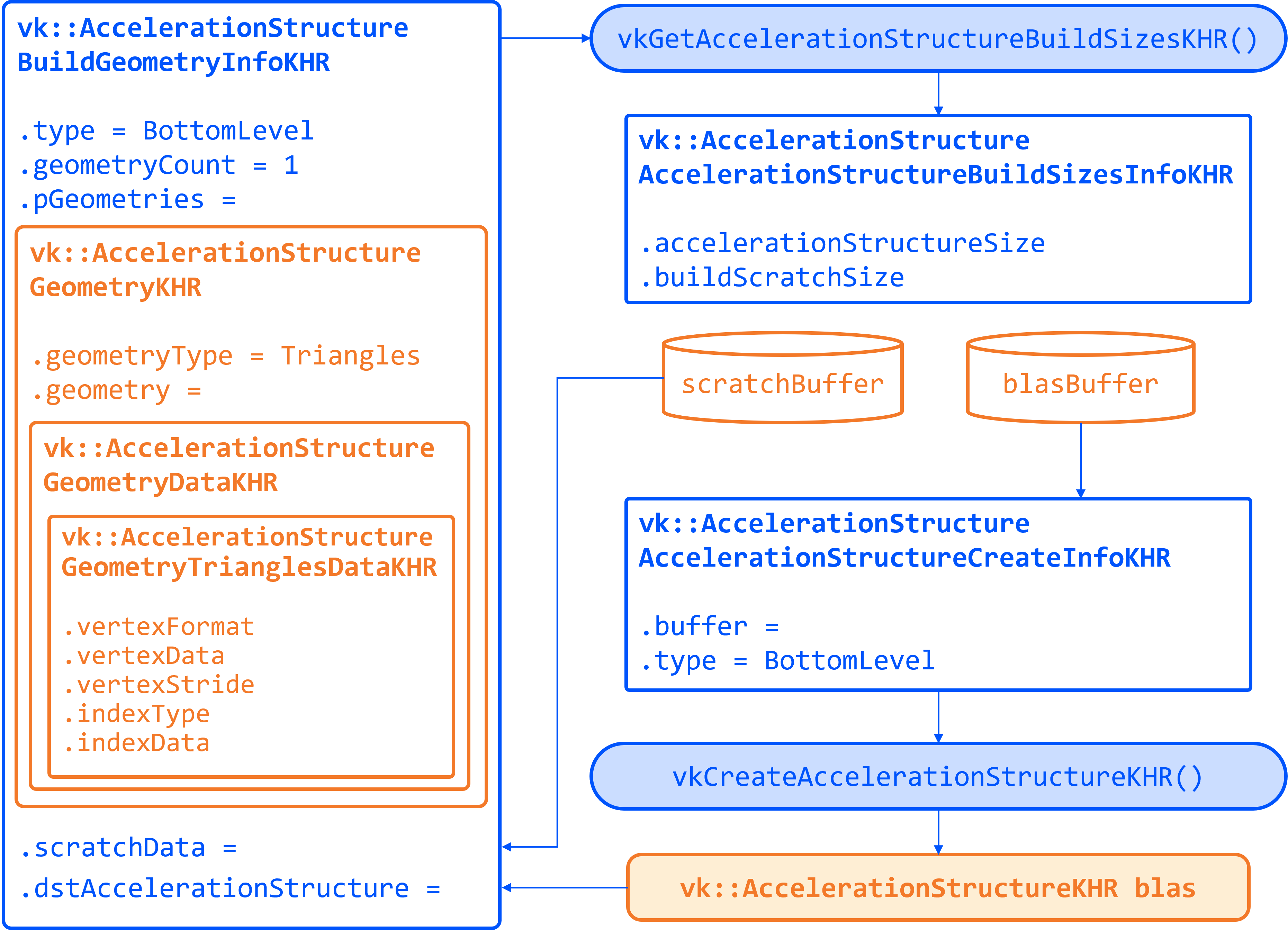
vk::AccelerationStructureGeometryTrianglesDataKHR triangles{
    .vertexFormat  = desc.vertex_format,
    .vertexData    = {.deviceAddress = vertex_buffer.address + vertex_offset},
    .vertexStride  = desc.vertex_stride,
    .maxVertex     = vertex_count - 1,
    .indexType     = desc.index_type,
    .indexData     = {.deviceAddress = index_buffer.address + index_offset},
    .transformData = {.deviceAddress = 0},  // 不提供额外几何变换,使用单位变换
};

vk::AccelerationStructureGeometryKHR geometry{
    .geometryType = vk::GeometryTypeKHR::eTriangles,
    .geometry     = {.triangles = triangles},
    .flags        = vk::GeometryFlagBitsKHR::eOpaque,
};

vk::AccelerationStructureBuildRangeInfoKHR range{
    .primitiveCount = index_count / 3,
};
示例假设索引三角形列表非空,地址已包含数据偏移。
maxVertex是最大顶点索引,vertexStride是顶点步长(字节)。输入 buffer 需要
eAccelerationStructureBuildInputReadOnlyKHR、eShaderDeviceAddress及设备地址分配支持。eOpaque用于不透明几何;使用 any-hit 做 alpha test 时,需要检查几何、实例和射线的不透明性标志。查询构建大小
build_info指定 AS 类型、构建模式、优化标志和输入几何。vk::AccelerationStructureBuildGeometryInfoKHR build_info{ .type = vk::AccelerationStructureTypeKHR::eBottomLevel, .flags = vk::BuildAccelerationStructureFlagBitsKHR::ePreferFastTrace, .mode = vk::BuildAccelerationStructureModeKHR::eBuild, .geometryCount = 1, .pGeometries = &geometry, }; vk::AccelerationStructureBuildSizesInfoKHR sizes_info{}; const uint32_t max_primitive_count = range.primitiveCount; device.getAccelerationStructureBuildSizesKHR( vk::AccelerationStructureBuildTypeKHR::eDevice, &build_info, &max_primitive_count, &sizes_info);多个 geometry 需要对应的 geometry、range 和最大图元数量数组。
geometryCount是几何数量,不是 buffer 数量。查询返回三种大小:
字段 用途 accelerationStructureSizeAS 构建结果所需的存储空间 buildScratchSizeBUILD 操作所需的临时工作空间 updateScratchSizeUPDATE 操作所需的临时工作空间 AS 内部布局由驱动管理。常见的构建标志选择如下:
类型 常见选择 原因 静态 BLAS ePreferFastTrace构建少、遍历多 动态 BLAS ePreferFastBuild几何频繁变化 TLAS ePreferFastBuild实例通常频繁变化 实际选择取决于构建与遍历的总耗时。UPDATE 和 COMPACT 分别要求初始构建加入
eAllowUpdate、eAllowCompaction。分配存储
auto as_buffer = createBuffer(
    sizes_info.accelerationStructureSize,
    vk::BufferUsageFlagBits::eAccelerationStructureStorageKHR |
        vk::BufferUsageFlagBits::eShaderDeviceAddress);

vk::AccelerationStructureCreateInfoKHR create_info{
    .buffer = as_buffer.buffer,
    .offset = 0,
    .size   = sizes_info.accelerationStructureSize,
    .type   = vk::AccelerationStructureTypeKHR::eBottomLevel,
};
vk::AccelerationStructureKHR blas =
    device.createAccelerationStructureKHR(create_info);

const auto scratch_alignment =
    as_properties.minAccelerationStructureScratchOffsetAlignment;
auto scratch_buffer = createBuffer(
    sizes_info.buildScratchSize,
    vk::BufferUsageFlagBits::eStorageBuffer |
        vk::BufferUsageFlagBits::eShaderDeviceAddress,
    scratch_alignment);
创建 AS 对象不等于完成构建。 AS buffer 保存结果,scratch 提供临时空间。最终 scratch 地址必须对齐;手动偏移地址时,要为偏移后的完整区间预留空间。
执行构建
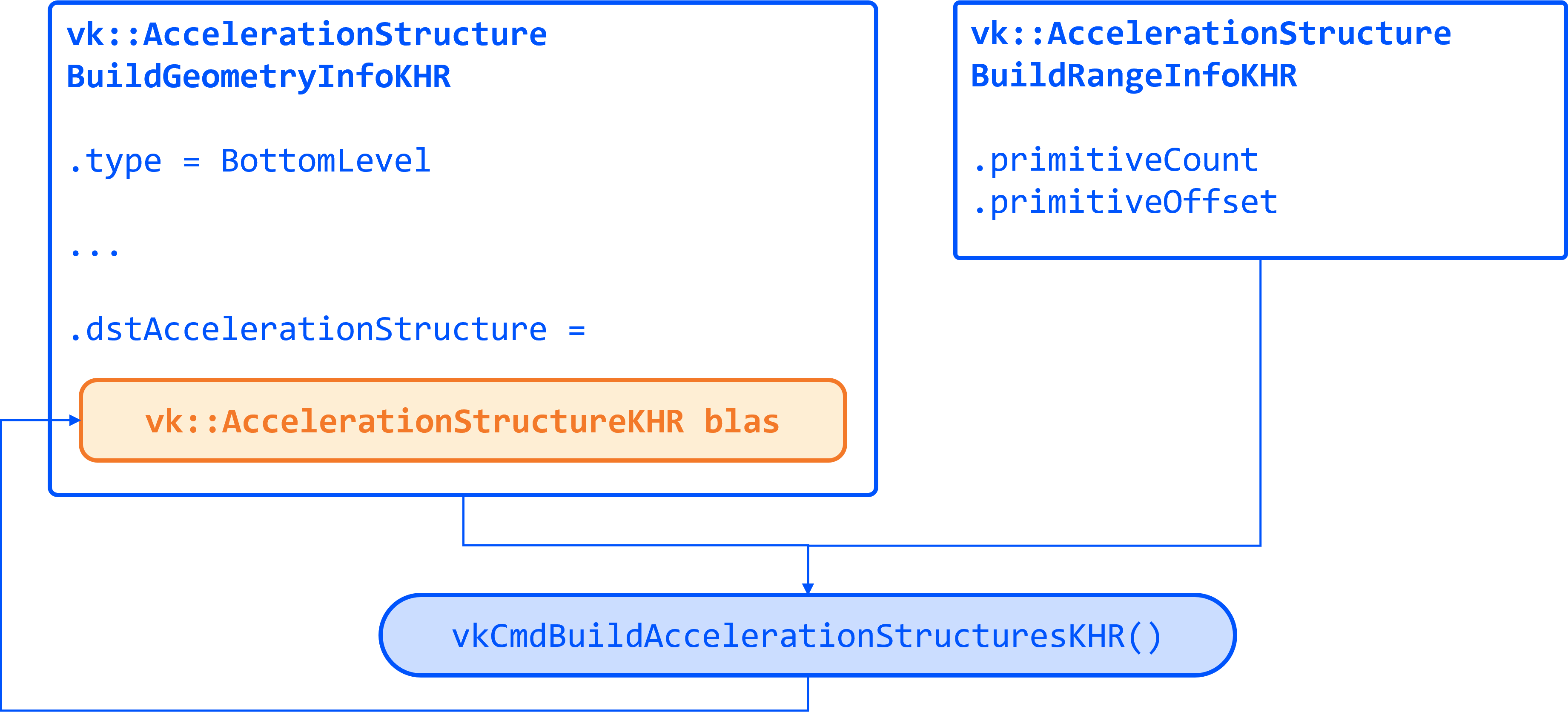
build_info.dstAccelerationStructure = blas;
build_info.scratchData.deviceAddress = scratch_buffer.address;

const vk::AccelerationStructureBuildRangeInfoKHR* ranges[] = {&range};
// 在记录构建命令前,建立输入数据写入 -> AS 构建读取的依赖。
command_buffer.buildAccelerationStructuresKHR(1, &build_info, ranges);

// 后续使用 AS 前,还需要相应的构建写入 -> 读取依赖。
submitAndWait(command_buffer);
destroyBuffer(scratch_buffer);
命令提交并完成后才能回收 scratch。示例直接等待,实际渲染器可用 fence 或 timeline semaphore 延迟回收。
3. 构建 TLAS
TLAS 的构建流程与 BLAS 相同,输入换成
vk::AccelerationStructureInstanceKHR数组。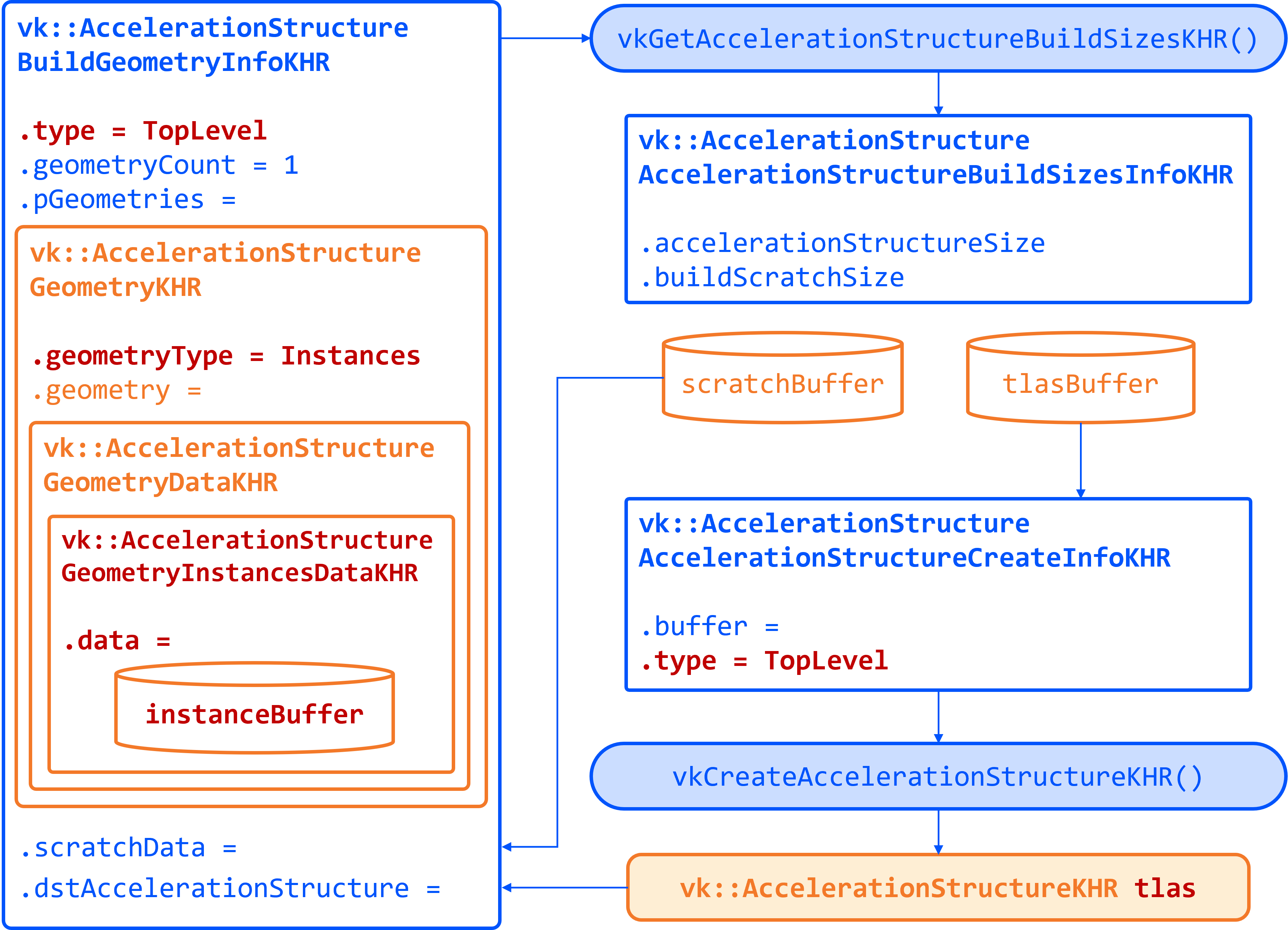
描述实例
vk::AccelerationStructureInstanceKHR instance{
    .transform                              = desc.transform_matrix,
    .instanceCustomIndex                    = desc.mesh_index,
    .mask                                   = 0xFF,
    .instanceShaderBindingTableRecordOffset = 0,
    .flags = static_cast<VkGeometryInstanceFlagsKHR>(
        vk::GeometryInstanceFlagBitsKHR::eTriangleFacingCullDisable),
    .accelerationStructureReference =
        device.getAccelerationStructureDeviceAddressKHR(
            vk::AccelerationStructureDeviceAddressInfoKHR{
                .accelerationStructure = blas,
            }),
};
字段 含义 transformBLAS 局部坐标到场景坐标的 3×4 矩阵,注意存储顺序 instanceCustomIndex应用定义的 24 位索引 mask与射线的 cull mask 按位与,结果为 0 时跳过实例 instanceShaderBindingTableRecordOffset命中组 SBT 索引计算中的记录偏移 accelerationStructureReferenceBLAS 的 AS 地址,不是 buffer 地址 将实例上传到具备
eAccelerationStructureBuildInputReadOnlyKHR和eShaderDeviceAddress用途的 buffer,并完成上传同步。描述实例数组并构建
vk::AccelerationStructureGeometryKHR instances_geometry{
    .geometryType = vk::GeometryTypeKHR::eInstances,
    .geometry = {
        .instances = {
            .arrayOfPointers = false,
            .data = {.deviceAddress = instances_buffer.address},
        },
    },
};

vk::AccelerationStructureBuildRangeInfoKHR tlas_range{
    .primitiveCount = instance_count,
};

vk::AccelerationStructureBuildGeometryInfoKHR tlas_build_info{
    .type          = vk::AccelerationStructureTypeKHR::eTopLevel,
    .flags         = vk::BuildAccelerationStructureFlagBitsKHR::ePreferFastBuild,
    .mode          = vk::BuildAccelerationStructureModeKHR::eBuild,
    .geometryCount = 1,
    .pGeometries   = &instances_geometry,
};
TLAS 的
geometryCount = 1,primitiveCount是实例数量,arrayOfPointers = false表示连续数组。随后查询大小、分配 TLAS 和 scratch,再执行构建。BLAS 构建与引用它的 TLAS 构建必须建立依赖,不能放在同一次 build 调用中。构建命令规则
4. UPDATE 与重建
初始构建包含
eAllowUpdate时,可在满足兼容条件的前提下执行 UPDATE。更新输入数据后,沿用原有 geometry、range 和构建参数:build_info.mode = vk::BuildAccelerationStructureModeKHR::eUpdate; build_info.srcAccelerationStructure = blas; build_info.dstAccelerationStructure = blas; // 原地更新 build_info.scratchData.deviceAddress = update_scratch_address; const vk::AccelerationStructureBuildRangeInfoKHR* ranges[] = {&range}; command_buffer.buildAccelerationStructuresKHR(1, &build_info, ranges);更新 scratch 仍需对齐,大小至少为
updateScratchSize。场景变化 通常需要处理的层级 物体平移、旋转或缩放,几何不变 更新或重建 TLAS,复用 BLAS 顶点位置改变,三角形连接关系不变 符合限制时 UPDATE BLAS;若实例包围范围变化,再更新或重建 TLAS 三角形连接关系、图元数量或 geometry 数量改变 重新 BUILD 对应 BLAS,并处理受影响的 TLAS 实例数量改变 重新 BUILD TLAS UPDATE 受格式、数量、拓扑和活动状态等兼容条件限制。大幅形变可能降低遍历效率,应同时评估重建成本与 trace 性能。
5. BLAS 压缩
初始构建包含
eAllowCompaction后,可以查询压缩大小,再用 COMPACT copy 生成更紧凑的 BLAS:构建 BLAS(ALLOW_COMPACTION) → 写入 compacted-size query → 等待并读取查询结果 → 分配目标存储并创建新 BLAS → 记录 COMPACT copy → 完成复制并切换引用 → 安全回收旧 BLAS 与旧存储查询压缩后的大小
创建
eAccelerationStructureCompactedSizeKHRquery pool,确保 BLAS 构建结果可见后查询:command_buffer.resetQueryPool(compaction_query_pool, 0, 1); command_buffer.writeAccelerationStructuresPropertiesKHR( 1, &blas, vk::QueryType::eAccelerationStructureCompactedSizeKHR, compaction_query_pool, 0); submitAndWait(command_buffer); vk::DeviceSize compacted_size = 0; const vk::Result query_result = device.getQueryPoolResults( compaction_query_pool, 0, 1, sizeof(compacted_size), &compacted_size, sizeof(compacted_size), vk::QueryResultFlagBits::e64 | vk::QueryResultFlagBits::eWait);检查查询结果,按
compacted_size分配存储并创建compacted_blas;收益不明显时可跳过压缩。复制并切换引用
vk::CopyAccelerationStructureInfoKHR copy_info{
    .src  = blas,
    .dst  = compacted_blas,
    .mode = vk::CopyAccelerationStructureModeKHR::eCompact,
};
command_buffer.copyAccelerationStructureKHR(copy_info);
submitAndWait(command_buffer);
COMPACT 是 AS 专用复制操作,不能用普通 buffer copy 代替。复制命令说明
压缩后 BLAS 地址改变。 最好先压缩,再构建 TLAS;已有 TLAS 则需换用新地址并更新或重建。复制和旧 AS 的在途操作结束后,才能回收旧存储。压缩期间新旧存储同时存在,需考虑显存峰值。
延伸阅读
- Vulkan 官方教程:Acceleration Structures:BLAS/TLAS 的基础构建流程。
- NVIDIA Vulkan Ray Tracing Tutorial:Acceleration Structures:结合 sample 理解构建与资源管理。
- nvpro_core2 acceleration_structures.hpp:构建、批处理与压缩的 helper 接口。
- NVIDIA RTXMU:面向光追加速结构的内存管理库。
- PSO
…
Tackling PSO Explosion in Vulkan: From Pipeline Caches to Shader Objects
A renderer may use only a modest number of shaders and still end up managing thousands of graphics pipelines. Different combinations of shader stages, vertex formats, attachment formats, and fixed-function state can quickly multiply into a large collection of pipeline state objects.
Vulkan provides several ways to manage this cost. Pipeline caches reuse previous compilation work, dynamic state reduces the number of required variants, graphics pipeline libraries share work across pipelines, and shader objects let applications bind shader stages independently.
Each approach addresses a different part of the problem.
Why PSO Counts Grow So Quickly
In this article, a PSO refers to a graphics
VkPipeline. For a typical vertex-and-fragment rendering path, it combines shader stages with vertex input, rasterization, depth/stencil, multisampling, and blending state.A simplified model is:
Graphics pipeline =
    shader stages
  + fixed-function state
  + resource interface
  + rendering compatibility information
Suppose a renderer needs 30 vertex shader variants, 40 fragment shader variants, and 25 fixed-function state combinations. If every combination is used, it needs:
30 × 40 × 25 = 30,000 graphics pipelinesThis is an illustrative upper bound: real renderers usually use only a subset of all possible combinations. Nevertheless, the multiplicative growth is the central problem.
Creating these pipelines through
vkCreateGraphicsPipelines()can involve translating SPIR-V into GPU machine code and optimizing it for the pipeline configuration. If that work happens on the rendering thread when a new combination first appears, it can cause a visible hitch. Compilation cost varies with the shader, driver, hardware, and available caches.MJP’s The Shader Permutation Problem provides a useful explanation of how rendering features and material systems generate these combinations.
Pipeline Precaching and Pipeline Caches
A common response is to move compilation out of gameplay.
During development and testing, the application records the pipeline configurations it encounters. On the player’s machine, it creates those pipelines during startup or loading screens. This approach, usually called PSO precaching, trades additional loading time for fewer compilation stalls during rendering.
Vulkan’s
VkPipelineCachecomplements this process. It allows the driver to reuse implementation-specific data across pipeline creation calls. Applications can retrieve that data withvkGetPipelineCacheData(), save it to disk, and provide compatible data on a later run.These mechanisms serve different purposes:
Mechanism What it provides PSO precaching Knowledge of which pipelines to create ahead of time VkPipelineCacheReusable driver data that may make creation cheaper A pipeline cache does not restore live
VkPipelinehandles, and it does not eliminate the need to create the requested pipelines. Its data is also implementation-specific, so a saved cache should not be treated as a universally portable compiled asset. See the Vulkan pipeline cache guide.Dynamic State: Reducing the Number of Variants
Before making pipeline creation faster, it is worth reducing how many pipelines need to exist.
Extended dynamic state allows more state to be specified while recording commands instead of being fixed at pipeline creation. For example, when cull mode is dynamic, changing from back-face culling to no culling does not require a separate pipeline solely for that difference:
vkCmdBindPipeline(cmd, VK_PIPELINE_BIND_POINT_GRAPHICS, pipeline);

vkCmdSetCullMode(cmd, VK_CULL_MODE_BACK_BIT);
vkCmdDraw(cmd, ...);

vkCmdSetCullMode(cmd, VK_CULL_MODE_NONE);
vkCmdDraw(cmd, ...);
The pipeline must declare the relevant state as dynamic, and the required features must be supported and enabled. Extensions such as
VK_EXT_extended_dynamic_state,VK_EXT_extended_dynamic_state2, andVK_EXT_extended_dynamic_state3expand the set of available controls. Vulkan dynamic state guideDynamic rendering is a separate feature.
VK_KHR_dynamic_renderingremoves the need to create traditional render pass and framebuffer objects for that rendering path. It does not, by itself, make rasterization, depth, or blending state dynamic.Dynamic state reduces combinations caused by fixed-function settings. Shader permutations still need their own solution.
Graphics Pipeline Libraries: Reusing Compilation Work
VK_EXT_graphics_pipeline_library, commonly abbreviated as GPL, divides a graphics pipeline into four reusable subsets:Library Main contents Vertex Input Interface Vertex input and input assembly Pre-Rasterization Shaders Pre-rasterization shader stages and associated state Fragment Shader Fragment shader and associated state Fragment Output Interface Color blending, output compatibility, and associated multisample state This is a conceptual overview; the exact state ownership follows the extension’s rules. GPL libraries contain more than shader bytecode, so their cache keys must capture all relevant state. GPL proposal
The application creates or retrieves the required libraries, then links them into an executable pipeline:
// Simplified application-level flow.
VkPipeline libraries[] = {
    getVertexInputLibrary(vertexInputKey),
    getPreRasterLibrary(preRasterKey),
    getFragmentShaderLibrary(fragmentKey),
    getFragmentOutputLibrary(fragmentOutputKey),
};

VkPipeline pipeline = linkLibraries(libraries, enableLTO);
For the earlier example, assume that:
- Vertex input is shared by every pipeline.
- The 30 vertex variants require 30 pre-rasterization libraries.
- The 40 fragment variants require 40 fragment shader libraries.
- All 25 state combinations belong to the fragment output subset.
The application can then reuse:
1 + 30 + 40 + 25 = 96 librariesIt may still need 30,000 executable pipeline combinations, but those pipelines share their constituent libraries.
That distinction explains GPL’s value: it separates reusable compilation work from the final combination step. It does not automatically reduce the number of executable pipelines the application requests.
Fast Linking and Link-Time Optimization
GPL supports a tradeoff between link cost and optimization opportunity.
Setting
VK_PIPELINE_CREATE_LINK_TIME_OPTIMIZATION_BIT_EXTrequests link-time optimization, or LTO. Libraries intended for this path must have been created withVK_PIPELINE_CREATE_RETAIN_LINK_TIME_OPTIMIZATION_INFO_BIT_EXT.The device property
graphicsPipelineLibraryFastLinkingdescribes the non-LTO path. When it is true, creating a pipeline entirely from libraries without LTO has a cost comparable to recording a command. It does not promise that LTO linking is equally cheap. Fast-linking propertyOne strategy is to create a non-LTO pipeline when needed, then build an optimized replacement on a background thread. Khronos describes this approach in its GPL integration article.
This also explains why enabling GPL may produce a smaller improvement than expected: repeatedly rebuilding libraries, using overly broad cache keys, or performing LTO for every final combination can preserve much of the original cost.
Shader Objects: Binding Stages Independently
VK_EXT_shader_objectchanges the application-facing model more directly.Instead of creating an executable graphics pipeline for each combination, the application creates
VkShaderEXTobjects and binds the required shader stages. Fixed-function state is supplied through command-buffer commands. Graphics shader objects are used with dynamic rendering. Khronos shader object sampleIn the LVK sample, the draw setup becomes:
buf.cmdBindShaderEXT(VK_SHADER_STAGE_VERTEX_BIT, vertex.get());
buf.cmdBindShaderEXT(VK_SHADER_STAGE_FRAGMENT_BIT, fragment.get());

// Application helper that establishes baseline dynamic state.
buf.cmdSetShaderObjectDefaults();

buf.cmdSetVertexInput(vertexInput_);
buf.cmdSetCullMode(lvk::CullMode_Back);
buf.cmdBindDepthState({
    .compareOp = lvk::CompareOp_Less,
    .isDepthWriteEnabled = true,
});
buf.cmdSetDepthBiasEnable(false);
Here,
cmdSetShaderObjectDefaults()is an application helper, not a Vulkan API. It initializes the required baseline state and explicitly unbinds unused shader stages.The remaining setup—resource binding, push constants, vertex/index buffers, and drawing—still has to be recorded.
This model allows a vertex shader to be reused with multiple compatible fragment shaders without creating a graphics pipeline for every pairing. Shader compilation still exists, and stage interfaces and resource layouts must remain compatible. Shader objects can also be linked at creation time when the application wants a linked group rather than freely interchangeable stages. Shader object specification
Native Support and the Compatibility Layer
Khronos also provides a shader object implementation in Vulkan-ExtensionLayer.
The layer translates shader object operations into pipeline operations, using dynamic state and GPL where available. It can therefore simplify the application’s rendering interface even when the underlying implementation still manages pipelines.
Native support and layer-based support should be measured separately. Using the same API does not mean both paths have identical compilation or runtime costs. The base
VK_EXT_shader_objectextension also does not replace ray tracing pipelines. Khronos shader object overviewComparing the Approaches
Approach Primary benefit Work that remains PSO precaching Moves pipeline creation into loading periods Discovering and creating required combinations Pipeline cache Reuses previous driver compilation data Pipeline creation and cache misses Dynamic state Removes variants caused by selected state changes Shader permutations and remaining static state GPL Shares libraries across executable pipelines Library creation and final linking Shader objects Removes the application’s need for graphics PSO combinations Shader creation, interface compatibility, and dynamic state management For a useful benchmark, measure library creation and final linking separately, distinguish LTO from non-LTO, and report whether application and driver caches are warm. Passing
VK_NULL_HANDLEas theVkPipelineCacheonly removes the explicit application-provided cache; it does not establish that the driver has no reusable internal data.The practical target is predictable frame time. A renderer benefits most when expensive compilation happens early, reusable work stays reusable, and encountering a new draw configuration does not block the frame.
Read More
- Self Intersection
…
Ray Tracing Gems: A Fast and Robust Method for Avoiding Self- Intersection
在光线追踪中,从表面交点继续发射阴影、反射或折射光线时,新光线有时会立刻再次命中当前表面,从而产生异常黑斑、条纹等自遮挡现象。这通常不是真实的遮挡,而是浮点数误差引起的自相交(Self-Intersection):自相交是原因,自遮挡是最终表现。
光线与三角形求交后,我们会根据交点参数或重心坐标重建交点位置 $p$。在精确数学中,$p$ 应当位于三角形平面上;但受浮点数精度限制,计算结果可能略高于或略低于真实表面。如果交点落在表面下方,从该点发射的次级光线就可能再次命中当前三角形或相邻三角形。
常见方法及其局限
1. 忽略当前三角形
记录当前命中的三角形 ID,并在次级光线再次命中相同 ID 时忽略该交点。这种方法实现简单,但存在以下问题:
- 在掠射角(Grazing Angle)下,光线可能命中相邻三角形,而不是原三角形;
- 无法正确处理重叠、共面或距离非常近的几何体;
- 某些情况下,光线本来就应该再次命中同一个三角形。
2. 设置固定的
tMin将光线的有效区间设置为 $t \in [\varepsilon, t_{\max}]$,忽略距离原点小于 $\varepsilon$ 的交点。
固定的 $\varepsilon$ 不具备尺度不变性:对于大型或远离原点的场景,它可能太小;对于微小、紧密的几何结构,它又可能太大。此外,在掠射角下,光线沿几何法线方向产生的实际位移很小,因此光线仍可能位于表面下方。
3. 沿着色法线偏移
着色法线(Shading Normal)通常由顶点法线插值得到,主要用于获得平滑的光照效果。它不一定与真实三角形平面正交,因此沿着色法线偏移,可能无法以最短距离离开表面,甚至可能把交点移动到几何体内部。
沿几何法线进行自适应偏移
几何法线(Geometric Normal)始终垂直于三角形平面。与其他方向相比,沿几何法线偏移能够以更小的位移离开表面,因此更适合用来修正次级光线的起点。
这里不能简单地使用固定偏移。浮点数保持的是近似固定的相对精度,而不是固定的绝对精度:坐标的绝对值越大,相邻可表示浮点数之间的间隔也越大。因此,交点离世界坐标原点越远,重建交点时的绝对误差通常越大;三角形尺寸越大,参与计算的数值越大,也可能进一步放大误差。
换句话说,可靠的偏移量应当同时适应交点坐标和几何尺寸的数量级,而不能依赖一个对所有场景都相同的固定
Bias。图片占位符
实现时,我们不直接给交点坐标加上固定的小数,而是将每个浮点分量的二进制表示重新解释为整数,再根据几何法线的方向移动若干个浮点刻度,也就是 ULP。
浮点数相邻刻度的间隔会随着数值大小自动变化,因此,同样的整数刻度偏移会产生不同的实际位移:
- 坐标较小时,实际偏移较小;
- 坐标较大时,实际偏移也会相应增大。
这样,偏移量便能自动适应交点坐标的数量级,无须针对不同场景手动调整参数。
接近零的位置需要单独处理。此时,通过整数表示移动若干刻度产生的位移可能小得不足以覆盖求交误差。因此,对于绝对值小于阈值的坐标分量,代码会直接沿几何法线增加一个很小的固定浮点偏移。三个坐标分量需要分别判断,因为同一个交点可能同时包含接近零和数值很大的分量。
下面代码中的常量来自实验测得的最大误差,并额外保留了一定的安全裕度:
constexpr float origin()      { return 1.0f / 32.0f; }
constexpr float float_scale() { return 1.0f / 65536.0f; }
constexpr float int_scale()   { return 256.0f; }

// n 为朝向次级光线发射侧的几何法线
float3 offset_ray(const float3 p, const float3 n)
{
    int3 of_i(
        int_scale() * n.x,
        int_scale() * n.y,
        int_scale() * n.z
    );

    float3 p_i(
        int_as_float(float_as_int(p.x) + ((p.x < 0) ? -of_i.x : of_i.x)),
        int_as_float(float_as_int(p.y) + ((p.y < 0) ? -of_i.y : of_i.y)),
        int_as_float(float_as_int(p.z) + ((p.z < 0) ? -of_i.z : of_i.z))
    );

    return float3(
        fabsf(p.x) < origin() ? p.x + float_scale() * n.x : p_i.x,
        fabsf(p.y) < origin() ? p.y + float_scale() * n.y : p_i.y,
        fabsf(p.z) < origin() ? p.z + float_scale() * n.z : p_i.z
    );
}
方法的边界
自适应几何法线偏移可以显著降低自相交的概率,但仍然无法覆盖所有极端情况。
例如,对于又深又窄的缝隙,如果缝隙宽度小于偏移距离,那么沿几何法线移动光线原点时,可能直接越过对面的表面,或者把新的光线原点移动到同一物体或相邻物体内部。
图片占位符
这种问题体现了偏移策略本身的取舍:
- 偏移太小,无法可靠避开自相交;
- 偏移太大,又可能跳过非常细小的几何结构。
因此,该方法不能保证所有场景都绝对正确,但相比固定
Read MoretMin、忽略当前三角形或沿着色法线偏移,它具有更好的尺度适应性和稳定性。
- Normal Fix
…
实时光线追踪:法线修正和平滑
在玻璃光追中,法线处理的第一个问题是:Mesh 通常只记录朝向物体外部的法线,但光线既可能从空气进入玻璃,也可能从玻璃内部射向空气。
因此,每次命中表面时,都要先根据光线方向与几何法线的关系判断当前处于入射还是出射状态,再统一修正法线方向和折射率比例:
// 光线射入物体
dir_refl = reflect(r,  n);
dir_refr = refract(r, -n, eta);

// 光线射出物体
dir_refl = reflect(r, -n);
dir_refr = refract(r,  n, 1.0 / eta);
这里的关键不是单独翻转法线,而是让法线方向、入射介质和出射介质保持一致。否则可能得到错误的光线方向,甚至错误触发全反射。
法线平滑
法线处理的第二个问题来自低模曲面的平滑着色。玻璃侧面,尤其是在薄边和掠射角区域,三角形之间的法线变化较大;如果直接使用几何法线,容易出现明显的分面感。
图片占位符
实时渲染通常会根据交点的重心坐标,对三角形三个顶点的法线进行插值,得到平滑的着色法线。同时,我们还会保留由三角形边叉乘得到的几何法线:
geometricNormal = normalize(cross(p1 - p0, p2 - p0));这里需要明确两类法线的分工:
- 几何法线(Geometric Normal):代表三角形的真实朝向,用于判断表面内外、处理自相交,并校验新生成光线的方向。
- 着色法线(Shading Normal):用于材质计算,让低模曲面呈现平滑的视觉效果。
在大多数情况下,使用着色法线计算光照没有问题。但在薄边、低模曲面或掠射角区域,着色法线可能与几何法线偏差较大。此时,根据着色法线生成的反射或折射方向,可能落到真实几何表面的错误一侧,进而产生黑点、漏光、自相交或边缘闪烁。
因此,生成候选方向后,还需要同时使用两类法线进行半球校验。在法线已经统一朝向入射侧的前提下:
bool validReflection =
    dot(direction, shadingNormal) > 0.0 &&
    dot(direction, geometricNormal) > 0.0;

bool validRefraction =
    dot(direction, shadingNormal) < 0.0 &&
    dot(direction, geometricNormal) < 0.0;
如果方向不合法,可以将该采样贡献置零或重新采样。Blender Cycles 的微表面采样也采用了类似的双法线校验,避免平滑几何产生错误的反射和折射方向。
这一部分可以总结为:几何法线负责保证光线方向在物理上合法,着色法线负责保证表面在视觉上平滑;两者需要分工使用,并在发射新光线前完成一致性校验。
Read More参考: Blender Cycles hemisphere validation
- SVGF
…
SVGF
Demodulation
计算光照时忽略 BRDF 中的材质信息,避免引入高频变化。以 diffuse 为例:
\[\text{diffuse} = L \cdot \rho \cdot n \cdot l / \pi\] \[\text{demodulate albedo} = L \cdot n \cdot l / \pi\]Temporal Accumulation
和 TAA 的重投影类似,通过深度、法线和 Mesh ID 来 reject。
Variance Esitimation
在时间上积累像素亮度的一阶矩和二阶矩 $\mu_1$、$\mu_2$。
计算方差:
\[\operatorname{Var} = \mu_2 - \mu_1^2\]Edge-Avoiding Atrous Wavelets
Wavelet filter 用于大范围滤波。法线和深度作为 edge avoiding 算法的输入,避免模糊掉几何边缘。
\[\hat{c}_{i+1}(p) = \frac{ \sum_{q \in \Omega} h(q)\, w(p,q)\, \hat{c}_i(q) }{ \sum_{q \in \Omega} h(q)\, w(p,q) }\]vec3 sum = vec3(0); float weight_sum = 0; for q in neighborhood: float weight = wavelet_kernel(q) // atrous wavelelt * depth_weight(p, q) // edge stopping * normal_weight(p, q) * luminance_weight(p, q); sum += weight * color[q]; weight_sum += weight; color_out[p] = sum / weight_sum;墙壁的几何边缘不会被模糊掉。
Luminance Edge Stopping Function
通过上面计算的 variance,避免模糊掉阴影细节:
\[w(p,q) = \exp\left( - \frac{ \left| l_i(p) - l_i(q) \right| }{ \sqrt{ g_{3 \times 3}\left( \operatorname{Var}\left(l_i(p)\right) \right) } } \right)\]- Variance 大 → 噪声多 → 增大模糊,降低噪点。
- Variance 小 → 噪声小 → 减小模糊,保留细节。
不过由于 filter 中对 variance 提前做了一遍高斯模糊来降低空域的噪声,一些阴影的细节会出现被模糊的情况。
阴影区域不会被模糊掉。
ASVGF
ASVGF 解决拖影和细节丢失问题,生成一张 temporal gradient 图,估计当前帧和历史帧的变化梯度。
asvgf_gradient_reproject.comp
    -> 生成 gradient sample positions
path tracer
    -> 对这些位置产生 gradient samples
asvgf_gradient_img.comp
    -> 根据当前/历史亮度差生成 gradient image
asvgf_gradient_atrous.comp
    -> 把稀疏 gradient 扩散成可用的低分辨率 gradient field
asvgf_temporal.comp
    -> 读取 gradient,做 anti-lag
Temporal Accumulation & AntiLag
以 primary ray HF 为例,权重 alpha 受 temporal gradient 的变化影响:
if(temporal_sample_valid_diff)
{
    // Compute the antilag factors based on the gradients
    float antilag_alpha_hf = clamp(mix(1.0, global_ubo.flt_antilag_hf * grad_hf_spec.x, global_ubo.flt_temporal_hf), 0, 1);

    // Adjust the history length, taking the antilag factors into account
    // gradient大,hist_len_hf小,历史帧越容易被丢弃
    float hist_len_hf = min(temporal_moments_histlen_hf.b * pow(1.0 - antilag_alpha_hf, 10) + 1.0, 256.0);

    // Compute the blending weights based on history length, so that the filter
    // converges faster. I.e. the first frame has weight of 1.0, the second frame 1/2, third 1/3 and so on.
    float alpha_color_hf = max(global_ubo.flt_min_alpha_color_hf, 1.0 / hist_len_hf);
    float alpha_moments_hf = max(global_ubo.flt_min_alpha_moments_hf, 1.0 / hist_len_hf);

    // Adjust the blending factors, taking the antilag factors into account again
    alpha_color_hf = mix(alpha_color_hf, 1.0, antilag_alpha_hf);
    alpha_moments_hf = mix(alpha_moments_hf, 1.0, antilag_alpha_hf);

    // Blend!
    out_color_hf.rgb = mix(temporal_color_hf.rgb, color_curr_hf.rgb, alpha_color_hf);

    out_moments_histlen_hf.rg = mix(temporal_moments_histlen_hf.rg, spatial_moments_hf.rg, alpha_moments_hf);
    out_moments_histlen_hf.b = hist_len_hf;
}
q2rtx impl
在 G-Buffer 生成后,一个 compute shader pass reproject 到上一帧生成:
Read MoreimageStore(IMG_ASVGF_GRAD_SMPL_POS_A, pos_grad, uvec4(gradient_idx)); imageStore(IMG_ASVGF_GRAD_HF_SPEC_PING, pos_grad, vec4(found_prev_lum, 0, 0)); imageStore(IMG_ASVGF_RNG_SEED_A, ipos, texelFetch(TEX_ASVGF_RNG_SEED_B, found_pos_prev, 0)); imageStore(IMG_PT_NORMAL_A, ipos, texelFetch(TEX_PT_NORMAL_B, found_pos_prev, 0)); imageStore(IMG_PT_BASE_COLOR_A, ipos, texelFetch(TEX_PT_BASE_COLOR_B, found_pos_prev, 0)); imageStore(IMG_PT_METALLIC_A, ipos, texelFetch(TEX_PT_METALLIC_B, found_pos_prev, 0));
- Q2RTX codepath
…
Q2RTX codepath
#define MATERIAL_KIND_MASK           0xf0000000
#define MATERIAL_KIND_INVALID        0x00000000
#define MATERIAL_KIND_REGULAR        0x10000000
#define MATERIAL_KIND_CHROME         0x20000000
#define MATERIAL_KIND_WATER          0x30000000
#define MATERIAL_KIND_LAVA           0x40000000
#define MATERIAL_KIND_SLIME          0x50000000
#define MATERIAL_KIND_GLASS          0x60000000
#define MATERIAL_KIND_SKY            0x70000000
#define MATERIAL_KIND_INVISIBLE      0x80000000
#define MATERIAL_KIND_EXPLOSION      0x90000000
#define MATERIAL_KIND_TRANSPARENT    0xa0000000 // Transparent walls. Have a distortion effect applied.
#define MATERIAL_KIND_SCREEN         0xb0000000
#define MATERIAL_KIND_CAMERA         0xc0000000
#define MATERIAL_KIND_CHROME_MODEL   0xd0000000
#define MATERIAL_KIND_TRANSP_MODEL   0xe0000000 // Transparent models. No distortion, just "see through".


struct RayPayloadGeometry {
   vec2 barycentric;
   /* two packed 16 bit integers, buffer index in low 16 bits and
    * instance index in high 16 bits */
   int buffer_and_instance_idx;
   uint primitive_id;
   float hit_distance;
};

struct RayPayloadEffects {
   uvec2 transparency; // half4x16
   uint distances; // half2x16 - min and max
   uvec4 fog1; // half8x16: .xy = color.rgba; .z = t_min, t_max; .w = density: a and b for (a*t + b)
   uvec4 fog2; // same as fog1 but for a fog volume further away
#ifndef KHR_RAY_QUERY
   // Store TMax in the payload because gl_RayTmaxEXT changes while the ray is being traced.
   // See the GLSL_EXT_ray_tracing spec near "description for gl_RayTminEXT and gl_RayTmaxEXT"
   // https://github.com/KhronosGroup/GLSL/blob/master/extensions/ext/GLSL_EXT_ray_tracing.txt
   float rayTmax;
#endif
};

layout(location = RT_PAYLOAD_GEOMETRY) rayPayloadEXT RayPayloadGeometry ray_payload_geometry;
layout(location = RT_PAYLOAD_EFFECTS) rayPayloadEXT RayPayloadEffects ray_payload_effects;
// primary ray vkpt_pt_trace_primary_rays(trace_cmd_buf); // qvkCmdTraceRaysKHR(cmd_buf, // &raygen, // &miss_and_hit, // &miss_and_hit, // &callable, // width/2, height, depth); // 2 depth for checkerboard rendering, split vkpt_submit_command_buffer(); // indirect reflection/refraction if (ref_mode.reflect_refract > 0) vkpt_pt_trace_reflections(trace_cmd_buf, 0); // multiple reflection/refraction if (ref_mode.reflect_refract > 1) for (int pass = 0; pass < ref_mode.reflect_refract - 1; pass++) vkpt_pt_trace_reflections(trace_cmd_buf, pass + 1); // seperated svgf reprojected pass vkpt_asvgf_gradient_reproject(trace_cmd_buf); vkpt_pt_trace_lighting(trace_cmd_buf, ref_mode.num_bounce_rays); vkpt_submit_command_buffer(); vkpt_asvgf_filter(post_cmd_buf, cvar_pt_num_bounce_rays->value >= 0.5f); vkpt_interleave(post_cmd_buf); vkpt_taa(post_cmd_buf); vkpt_bloom_record_cmd_buffer(post_cmd_buf); vkpt_tone_mapping_record_cmd_buffer(); vkpt_fsr_do(post_cmd_buf); vkpt_submit_command_buffer_simple();primary_rays.rgen(path tracer overview的1)
 // generate primary ray information, including bias offset to get depth of field
Ray ray = get_primary_ray(inUV);


// primary ray -> path_tracer.rchit/path_tracer.rmiss
traceRayEXT( topLevelAS[TLAS_INDEX_GEOMETRY], rayFlags, instance_mask,
        SBT_RCHIT_GEOMETRY /*sbtRecordOffset*/, 0 /*sbtRecordStride*/, SBT_RMISS_EMPTY /*missIndex*/,
        ray.origin, ray.t_min, ray.direction, ray.t_max, RT_PAYLOAD_GEOMETRY);

Triangle triangle;

if (found_intersection(ray_payload_geometry)) // hit surface
{
    ray.t_max = ray_payload_geometry.hit_distance;
    triangle = get_hit_triangle(ray_payload_geometry);
}
// particle/explosion/sprite/beam
traceRayEXT( topLevelAS[TLAS_INDEX_EFFECTS], rayFlags, instance_mask,
        SBT_RCHIT_EFFECTS /*sbtRecordOffset*/, 0 /*sbtRecordStride*/, SBT_RMISS_EMPTY /*missIndex*/,
        ray.origin, ray.t_min, ray.direction, ray.t_max, RT_PAYLOAD_EFFECTS);

vec4 effects = get_payload_transparency_with_fog(ray_payload_effects, ray.t_max);

vec3 bary = get_hit_barycentric(ray_payload_geometry);

// store 2 visibility buffer
{
    uvec2 vis_buf;
    vis_buf.x = triangle.instance_index;
    vis_buf.y = triangle.instance_prim;
    imageStore(IMG_PT_VISBUF_PRIM_A, ipos, uvec4(vis_buf, 0, 0)); // rg32ui / R32G32_UINT
    imageStore(IMG_PT_VISBUF_BARY_A, ipos, vec4(bary.yz, 0, 0)); // rg16f / R16G16_SFLOAT
}

// get hit point information
vec3 position = triangle.positions * bary;
vec2 texcoord = triangle.texcoords * bary;
vec3 geo_normal = triangle.normals* bary;
vec3 flat_normal = normalize(cross(
        triangle.positions[1] - triangle.positions[0],
        triangle.positions[2] - triangle.positions[1]));

/* compute view-space derivatives of depth and motion vectors */
Ray ray_0 = get_primary_ray(inUV);
Ray ray_x = get_primary_ray(inUV + vec2(1.0 / float(global_ubo.width), 0));
Ray ray_y = get_primary_ray(inUV + vec2(0, 1.0 / float(global_ubo.height)));

// larger coneangle means high gradient, means higher mips
float half_cone_angle = sqrt(1.0 - square(min(
dot(ray_0.direction, ray_x.direction),
dot(ray_0.direction, ray_y.direction))));

vec2 tex_coord_x, tex_coord_y;
float fwidth_depth;
// get texure lod
compute_anisotropic_texture_gradients(position, flat_normal, ray.direction,
    ray_payload_geometry.hit_distance * half_cone_angle, triangle.positions,
    triangle.tex_coords, tex_coord, tex_coord_x, tex_coord_y, fwidth_depth);

vec3 pos_ws_curr = position;
vec3 pos_ws_prev = triangle.positions_prev * bary;
vec2 screen_pos_curr, screen_pos_prev;
float distance_curr, distance_prev;
projection_view_to_screen((global_ubo.V * vec4(pos_ws_curr, 1)).xyz, screen_pos_curr, distance_curr, false);
projection_view_to_screen((global_ubo.V_prev * vec4(pos_ws_prev, 1)).xyz, screen_pos_prev, distance_prev, true);

// motion vector
vec3 motion;
motion.xy = screen_pos_prev - screen_pos_curr;
motion.z = distance_prev - distance_curr;

imageStore(IMG_PT_VIEW_DEPTH_A, ipos, vec4(distance_curr));
imageStore(IMG_PT_MOTION, ipos, vec4(motion, fwidth_depth));

// Get the primary surface material parameters
get_material(
    triangle,
    bary,
    tex_coord,
    tex_coord_x,
    tex_coord_y,
    -1,
    geo_normal,
    primary_base_color,
    normal,
    primary_metallic,
    primary_roughness,
    primary_emissive,
    primary_specular_factor);

// get mat id
uint material_id = triangle.material_id;
...

// handle various material one by one

// write to gbuffer
// shading normal
imageStore(IMG_PT_NORMAL_A, ipos, uvec4(encode_normal(normal)));
// geo normal
imageStore(IMG_PT_GEO_NORMAL_A, ipos, uvec4(encode_normal(geo_normal)));
//...
imageStore(IMG_PT_SHADING_POSITION, ipos, vec4(position.xyz, uintBitsToFloat(material_id)));
//...
imageStore(IMG_PT_VIEW_DIRECTION, ipos, vec4(direction, float(checkerboard_flags)));
imageStore(IMG_PT_THROUGHPUT, ipos, vec4(throughput, distance_curr));
imageStore(IMG_PT_BOUNCE_THROUGHPUT, ipos, vec4(1, 1, 1, half_cone_angle));
imageStore(IMG_PT_CLUSTER_A, ipos, ivec4(triangle.cluster));
imageStore(IMG_PT_BASE_COLOR_A, ipos, vec4(primary_base_color, primary_specular_factor));
imageStore(IMG_PT_METALLIC_A, ipos, vec4(primary_metallic, primary_roughness, 0, 0));
imageStore(IMG_PT_GODRAYS_THROUGHPUT_DIST, ipos, vec4(1, 1, 1, distance_curr));
transparent = alpha_blend_premultiplied(effects, transparent);

imageStore(IMG_PT_TRANSPARENT, ipos, transparent);
reflect_refract.rgen
reflect_refract.rgen 会在 G-buffer 当前 surface 是 water / slime / glass / chrome / screen / camera / transparent 等特殊材质时,每像素沿 reflection 或 refraction 方向继续追一条 ray,并用命中的 secondary surface 更新 G-buffer / throughput / medium / motion。下面的 IOR + checkerboard 代码是抽象伪码;真实代码会按 material kind 分支处理 thin/thick glass、water/slime medium、total internal reflection、chrome/screen 只反射、transparent see-through 等情况。
// get shading pos
vec4 position_material = imageLoad(IMG_PT_SHADING_POSITION, ipos);

if(!( primary_is_water ||
      primary_is_slime ||
      primary_is_glass ||
      primary_is_chrome ||
      primary_is_screen ||
      primary_is_camera ||
      primary_is_transparent ))
    return;

index_of_refraction = get_mat_ior();
vec3 refracted_direction = refract(direction, normal, index_of_refraction);
float F = pow(1.0 - n_dot_v, 5.0);
do_refraction = is_odd_checkerboard && F < 1;
direction = do_refraction ? refract() : reflect();
correction_factor *= 2; // 补能量
throughput *= correction_factor;
primary_medium = new_medium;//更新介质

int reflection_cull_mask = REFLECTION_RAY_CULL_MASK|xxx;

Ray reflection_ray;
reflection_ray.origin = position;
reflection_ray.direction = direction;

trace_geometry_ray(reflection_ray, backface_culling, reflection_cull_mask);
Triangle triangle;

if (found_intersection(ray_payload_geometry))
{
    reflection_ray.t_max = ray_payload_geometry.hit_distance;
    triangle = get_hit_triangle(ray_payload_geometry);
}

vec4 effects = trace_effects_ray(reflection_ray, /* skip_procedural = */ false);

// almost same with primary ray
...
// update gbuffer
asvgf_gradient_reproject.comp
direct_lighting.rgen// direct diffuse + direct sun shadow
vec3 high_freq, specular;
direct_lighting(ipos, is_odd_checkerboard, high_freq, specular);

vec4 view_direction = texelFetch(TEX_PT_VIEW_DIRECTION, ipos, 0);
vec3 normal = decode_normal(texelFetch(TEX_PT_NORMAL_A, ipos, 0).x);
vec3 geo_normal = decode_normal(texelFetch(TEX_PT_GEO_NORMAL_A, ipos, 0).x);
vec4 primary_base_color = texelFetch(TEX_PT_BASE_COLOR_A, ipos, 0);
float primary_specular_factor = primary_base_color.a;
vec2 metal_rough = texelFetch(TEX_PT_METALLIC_A, ipos, 0).xy;
float primary_metallic = metal_rough.x;
float primary_roughness = metal_rough.y;
uint cluster_idx = texelFetch(TEX_PT_CLUSTER_A, ipos, 0).x;

vec3 primary_albedo, primary_base_reflectivity;
get_reflectivity(primary_base_color.rgb, primary_metallic, primary_albedo, primary_base_reflectivity);

// precompute phong coeff
float alpha = square(roughness);
float phong_exp = RoughnessSquareToSpecPower(alpha);
float phong_scale = min(100, 1 / (M_PI * square(alpha)));
float phong_weight = clamp(specular_factor * luminance(base_reflectivity) / (luminance(base_reflectivity) + luminance(albedo)), 0, 0.9);

/*
get_direct_illumination(
    position,
    normal,
    geo_normal,
    cluster_idx,
    material_id,
    shadow_cull_mask,
    view_direction.xyz,
    primary_albedo,
    primary_base_reflectivity,
    primary_specular_factor,
    primary_roughness,
    primary_medium,
    spec_enable_caustics != 0,
    direct_specular_weight,
    global_ubo.pt_direct_polygon_lights > 0,
    global_ubo.pt_direct_dyn_lights > 0,
    is_gradient,
    0,
    direct_diffuse,
    direct_specular);
*/

//  sample a static light
// 1. 重要性采样:从很多 polygon lights 里选一个 light
// float m = spherical_tri_area(light.positions, p, n, V, phong_exp, phong_scale, phong_weight);
// float light_lum = luminance(light.color);
// m *= abs(light_lum);
// 2. 几何采样:在这个 light 的三角形上选一个点
sample_polygonal_lights(
    cluster_idx,
    position,
    normal,
    geo_normal,
    view_direction,
    phong_exp,
    phong_scale,
    phong_weight,
    is_gradient,
    pos_on_light_polygonal,
    contrib_polygonal,
    polygonal_light_index,
    polygonal_light_pdfw,
    polygonal_light_is_sky,
    rng);
    // Limit the solid angle of sphere lights for indirect lighting
    // in order to kill some fireflies in locations with many sphere lights.
    // Example: green wall-lamp corridor in the "train" map.
    float max_solid_angle = (bounce == 0) ? 2 * M_PI : 0.02;

// sample a dynamic light
// dynamic lights 内部是在 num_dyn_lights 中 uniform 选一个 light,pdf = 1 / num_dyn_lights,
// sample_dynamic_lights 里会乘 num_dyn_lights 做 1/pdf 补偿;sphere/spot 的能量用 analytic irradiance 近似。
sample_dynamic_lights(
    position,
    normal,
    geo_normal,
    max_solid_angle,
    pos_on_light_dynamic,
    contrib_dynamic,
    rng);

float spec_polygonal = phong(normal, normalize(pos_on_light_polygonal - position), view_direction, phong_exp) * phong_scale;
float spec_dynamic = phong(normal, normalize(pos_on_light_dynamic - position), view_direction, phong_exp) * phong_scale;

// compute luminance of two light
float l_polygonal  = luminance(abs(contrib_polygonal)) * mix(1, spec_polygonal, phong_weight);
float l_dynamic = luminance(abs(contrib_dynamic)) * mix(1, spec_dynamic, phong_weight);
float l_sum = l_polygonal + l_dynamic;

bool null_light = (l_sum == 0);

float w = null_light ? 0.5 : l_polygonal / (l_polygonal + l_dynamic);

// random chose one, polygon or dynamic
float rng2 = get_rng(RNG_NEE_LIGHT_TYPE(bounce));
is_polygonal = (rng2 < w);
vis = is_polygonal ? (1 / w) : (1 / (1 - w));
vec3 pos_on_light = null_light ? position : (is_polygonal ? pos_on_light_polygonal : pos_on_light_dynamic);
vec3 contrib = is_polygonal ? contrib_polygonal : contrib_dynamic;

Ray shadow_ray = get_shadow_ray(position - view_direction * 0.01, pos_on_light, 0);

vis *= trace_shadow_ray(shadow_ray, null_light ? 0 : shadow_cull_mask);

// TODO, Adaptive Shadow Testing for Ray Tracing, Ward 1994 optimization

vec3 radiance = vis * contrib;

vec3 L = pos_on_light - position;
L = normalize(L);

// specular lighting

if(is_polygonal && direct_specular_weight > 0 && polygonal_light_is_sky && global_ubo.pt_specular_mis != 0)
{
    // MIS with direct specular and indirect specular.
    // Only applied to sky lights, for two reasons:
    //  1) Non-sky lights are trimmed to match the light texture, and indirect rays don't see that;
    //  2) Non-sky lights are usually away from walls, so the direct sampling issue is not as pronounced.

    direct_specular_weight *= get_specular_sampled_lighting_weight(roughness,
        normal, -view_direction, L, polygonal_light_pdfw);
}

vec3 F = vec3(0);

if(vis > 0 && direct_specular_weight > 0)
{
    vec3 specular_brdf = GGX_times_NdotL(view_direction, normalize(pos_on_light - position),
        normal, roughness, base_reflectivity, 0.0, specular_factor, F);
    specular = radiance * specular_brdf * direct_specular_weight;
}

float NdotL = max(0, dot(normal, L));

// diffuse lighting

float diffuse_brdf = NdotL / M_PI;
diffuse = radiance * diffuse_brdf * (vec3(1.0) - F);

high_freq += direct_diffuse;
o_specular += direct_specular;
/*
get_sunlight(
    cluster_idx,
    material_id,
    position,
    normal,
    geo_normal,
    view_direction.xyz,
    primary_base_reflectivity,
    primary_specular_factor,
    primary_roughness,
    primary_medium,
    spec_enable_caustics != 0,
    direct_sun_diffuse,
    direct_sun_specular,
    shadow_cull_mask);
*/
// similar with polygon/dynamic light computation

high_freq += direct_sun_diffuse;
o_specular += direct_sun_specular;

o_specular = demodulate_specular(primary_base_reflectivity, o_specular);

high_freq = clamp_output(high_freq);
o_specular = clamp_output(o_specular);

high_freq *= STORAGE_SCALE_HF;//32
o_specular *= STORAGE_SCALE_SPEC;//32
imageStore(IMG_PT_COLOR_LF_SH, ipos, vec4(0));
imageStore(IMG_PT_COLOR_LF_COCG, ipos, vec4(0));
imageStore(IMG_PT_COLOR_HF, ipos, uvec4(packRGBE(high_freq))); // diffuse
imageStore(IMG_PT_COLOR_SPEC, ipos, uvec4(packRGBE(o_specular))); // specular
indirect_lighting.rgen
// already have primary ray hit surface into
view_direction = texelFetch(TEX_PT_VIEW_DIRECTION, ipos, 0);
normal = decode_normal(texelFetch(TEX_PT_NORMAL_A, ipos, 0).x);
geo_normal = decode_normal(texelFetch(TEX_PT_GEO_NORMAL_A, ipos, 0).x);
primary_base_color = texelFetch(TEX_PT_BASE_COLOR_A, ipos, 0);
primary_specular_factor = primary_base_color.a;
vec2 metal_rough = texelFetch(TEX_PT_METALLIC_A, ipos, 0).xy;
primary_metallic = metal_rough.x;
primary_roughness = metal_rough.y;

get_reflectivity(primary_base_color.rgb, primary_metallic, primary_albedo, primary_base_reflectivity);
float NoV = max(0, -dot(normal, view_direction.xyz));
// 判断光线类型
bool is_specular_ray;

// compute the indirect ray direction towards ggx reflection lobe
if(spec_bounce_index == 0)
{
    specular_pdf = (primary_metallic == 1 && fake_specular_weight == 0) ? 1.0 : 0.5;

    // 50%概率进,specular path
    if(rng_frensel < specular_pdf)
    {
        mat3 basis = construct_ONB_frisvad(normal);

        // Sampling of normal distribution function to compute the reflected ray.
        // See the paper "Sampling the GGX Distribution of Visible Normals" by E. Heitz,
        // Journal of Computer Graphics Techniques Vol. 7, No. 4, 2018.
        // http://jcgt.org/published/0007/04/01/paper.pdf

        vec3 N = normal;
        vec3 V = view_direction.xyz;
        vec3 H = ImportanceSampleGGX_VNDF(rng3, primary_roughness, V, basis);
        vec3 L = reflect(V, H);

        float NoL = max(0, dot(N, L));
        float NoH = max(0, dot(N, H));
        float VoH = max(0, -dot(V, H));

        if (NoL > 0 && NoV > 0)
        {
            // See the Heitz paper referenced above for the estimator explanation.
            //   (BRDF / PDF) = F * G2(V, L) / G1(V)
            // Assume G2 = G1(V) * G1(L) here and simplify that expression to just G1(L).

            float G1_NoL = G1_Smith(primary_roughness, NoL);
            vec3 F = schlick_fresnel(primary_base_reflectivity, VoH, primary_specular_factor);

            bounce_throughput *= G1_NoL * F;

            bounce_throughput *= 1 / specular_pdf;
            is_specular_ray = true;
            bounce_direction = normalize(L);
        }
    }
}
// 发射diffuse光线
if(!is_specular_ray)
{
    vec3 basis_normal, dir_sphere;
#if ENABLE_SH
    if(spec_bounce_index == 0 && global_ubo.flt_enable != 0)
    {
        dir_sphere = sample_cos_hemisphere_multi(0, 1, rng3, HEMISPHERE_UNIFORMISH);
        basis_normal = geo_normal;
    }
    else
#endif
    {
        dir_sphere = sample_cos_hemisphere(rng3);
        basis_normal = normal;
    }

    mat3 basis = construct_ONB_frisvad(basis_normal);
    bounce_direction = normalize(basis * dir_sphere);
    // diffuse 和 specular 是互斥采样;这里除以选择 diffuse 的概率 (1 - specular_pdf) 做 1/pdf 补偿。
    bounce_throughput *= 1 / (1 - specular_pdf);

    vec3 L = bounce_direction.xyz;
    vec3 V = -view_direction.xyz;
    vec3 H = normalize(V + L);
    float VoH = max(0, dot(V, H));

    vec3 F = schlick_fresnel(primary_base_reflectivity, VoH, primary_specular_factor);

    bounce_throughput *= vec3(1.0) - F;
}

Ray bounce_ray;
bounce_ray.origin = position;
bounce_ray.direction = bounce_direction;
bounce_ray.t_min = 0;
bounce_ray.t_max = 10000;

trace_geometry_ray(bounce_ray, true, bounce_cull_mask);

// specular ray 再 trace 特效
if(is_specular_ray)
{
    if (found_intersection(ray_payload_geometry))
        bounce_ray.t_max = ray_payload_geometry.hit_distance;

    vec4 transparency = trace_effects_ray(bounce_ray, /* skip_procedural = */ true);
    bounce_contrib += transparency.rgb * transparency.a * bounce_throughput * (1.0 - direct_specular_weight);
}
Triangle triangle = get_hit_triangle(ray_payload_geometry);

// hit surface properties
vec3 bary         = get_hit_barycentric(ray_payload_geometry);
vec2 tex_coord    = triangle.tex_coords * bary;
uint bounce_material_id = triangle.material_id;
position;
normal;
geo_normal;
basecolor;
...

 vec3 emissive = sample_emissive_texture(triangle.material_id, bounce_minfo, tex_coord, vec2(0), vec2(0), is_specular_ray ? 2 : 3);
 emissive += get_emissive_shell(triangle.material_id, triangle.shell) * bounce_base_color;
 // other emissive login

 // 1 bounce gi
 vec3 bounce_diffuse, bounce_specular;
get_direct_illumination(
    bounce_position,
    bounce_geo_normal,
    bounce_geo_normal,
    bounce_cluster_idx,
    bounce_material_id,
    shadow_cull_mask,
    bounce_direction,
    bounce_base_color,
    vec3(0), // base_reflectivity
    0.0, // specular_factor
    1.0, // roughness
    MEDIUM_NONE,
    false, // enable_caustics
    0.0, // direct_specular_weight
    global_ubo.pt_indirect_polygon_lights > 0,
    global_ubo.pt_indirect_dyn_lights > 0,
    is_gradient,
    1, // bounce
    bounce_diffuse,
    bounce_specular);

bounce_contrib += bounce_throughput * bounce_diffuse;

imageStore(IMG_PT_GEO_NORMAL2, ipos, uvec4(encode_normal(bounce_geo_normal)));
imageStore(IMG_PT_SHADING_POSITION, ipos, vec4(bounce_position.xyz, uintBitsToFloat(triangle.material_id)));
imageStore(IMG_PT_VIEW_DIRECTION2, ipos, vec4(bounce_direction, 0));
imageStore(IMG_PT_BOUNCE_THROUGHPUT, ipos, vec4(bounce_throughput, is_specular_ray ? 1 : 0));

// denoise without f0
if (is_specular_ray)
    bounce_contrib = demodulate_specular(primary_base_reflectivity, bounce_contrib);

if(is_specular_ray)
{
    bounce_contrib *= STORAGE_SCALE_SPEC;

    vec3 specular = unpackRGBE(imageLoad(IMG_PT_COLOR_SPEC, ipos).x);
    specular += bounce_contrib;
    imageStore(IMG_PT_COLOR_SPEC, ipos, uvec4(packRGBE(specular)));
}
else
{
    bounce_contrib *= STORAGE_SCALE_LF;

    SH low_freq = load_SH(TEX_PT_COLOR_LF_SH, TEX_PT_COLOR_LF_COCG, ipos);

#if ENABLE_SH
    if(global_ubo.flt_enable == 0)
        low_freq.shY.xyz += bounce_contrib;
    else
    {
        accumulate_SH(low_freq, irradiance_to_SH(bounce_contrib, bounce_direction), 1.0);
    }
#else
    low_freq.shY.xyz += bounce_contrib;
#endif

    STORE_SH(IMG_PT_COLOR_LF_SH, IMG_PT_COLOR_LF_COCG, ipos, low_freq);
}
总结
Diffuse GI 比较低频,Q2RTX 的 LF 通道不是完整 RGB SH,而是压缩成:
- PT_COLOR_LF_SH:一阶 SH,也就是 L0 + L1 的 4 个系数,只存 Y/luma 的方向性。
- PT_COLOR_LF_COCG:存 Co/Cg 色度,不存方向性,近似为平均 tint。
- RGB 会先转到 YCoCg:Co = R - B,t = B + Co * 0.5,Cg = G - t,Y = t + Cg * 0.5。
- SH 写入形式是:result.CoCg = vec2(Co, Cg),result.shY = vec4(L11, L1_1, L10, L00) * Y。
- 后续 ASVGF 滤波的是 SH + CoCg 这个 lighting representation;normal/depth 不被滤波,但会作为 edge-aware guide 参与滤波权重。最终 composite 前再用当前像素 normal 调用 project_SH_irradiance(filtered_lf, normal),把 LF SH 投影回 RGB irradiance。
Checkerboard field 不是单纯半分辨率优化 Q2RTX 把最终屏幕的 checkerboard pixels de-interleave 到左右半屏:左半是 even field,右半是 odd field。这样每个 field 都是 dense image,便于 denoiser 做空间滤波;同时 reflection/refraction 可以分到不同 field,例如一半 field 走 reflection,一半 field 走 refraction。后续再用 checkerboard_interleave.comp 合回 flat image。
Reflect/Refract pass 是 specular guide path,不只是视觉反射 reflect_refract.rgen 会把水、玻璃、chrome、screen 等特殊材质后面看到的 secondary surface 写回 G-buffer,包括 position、normal、base color、material、visbuffer、motion/depth 等。这样后续 direct/indirect lighting 和 denoiser 看到的是“镜子/玻璃后面的表面”,而不是只有 primary glass/mirror surface。
Ray cone / texture LOD 是 secondary ray 质量关键 Primary pass 用相邻像素 primary ray 的夹角估计 half_cone_angle,secondary hit 时用 hit_distance * half_cone_angle 估算 footprint,再调用 compute_anisotropic_texture_gradients 计算纹理 LOD。否则反射/间接命中后的贴图采样会过锐、闪烁或 alias。
Path throughput 是跨 pass 的能量账本 IMG_PT_THROUGHPUT / IMG_PT_BOUNCE_THROUGHPUT 记录 reflection/refraction、medium extinction、Fresnel sampling correction、BRDF sampling correction 等路径权重。后续 lighting pass 算到的 radiance 都要乘这个 throughput 才是对 camera pixel 的贡献。
Specular demodulation 提高 denoiser 稳定性 SPEC channel 在写入前会用 demodulate_specular(base_reflectivity, specular) 除掉材质 F0/specular color,滤波后 composite 再用 modulate_specular 乘回去。这样 denoiser 处理的是更像“光照强度”的信号,而不是光照和金属颜色/贴图细节混在一起的结果。
One-sample NEE + 重要性采样,比遍历所有灯更适合实时 get_direct_illumination 每个 shading point 通常只打一条 shadow ray:先在 polygon lights 中 importance sample 一个候选,再 uniform sample 一个 dynamic light 候选,然后按贡献估计在 polygon/dynamic 之间二选一,并用 1/pdf 补偿。这样一个样本统计上代表整个候选灯集合。
Light shadow statistics 是低成本的下一帧采样反馈 Q2RTX 会统计每个 cluster / light / surface orientation 上 shadow ray 是 unshadowed 还是 shadowed,下一帧在 sample_polygonal_lights 里降低经常被挡住的灯的 mass,但保留下限避免完全不采。
Geometry TLAS 和 Effects TLAS 分离 Q2RTX 把真实几何和粒子、爆炸、sprite、beam 等 effects 放到不同 TLAS。Primary/secondary geometry ray 先找 surface,再用 effects ray 累积透明特效。这样普通 visibility 不必总是遍历 effects,也能给 effects 使用不同 hit shader / any-hit 逻辑。
Half-res GI profile 不是简单降分辨率,而是降低路径复杂度 pt_num_bounce_rays == 0.5 时,indirect pass 只在隔行像素上跑,并且默认不读取真实 metallic/roughness,等价于低质量 diffuse GI profile,避免半分辨率 specular 带来闪烁和错误重建。
Ray Query / RT Pipeline 双路径值得保留抽象边界 Q2RTX 同一套 rgen 逻辑会编译成 .pipeline.spv 和 .query.spv。RT pipeline 路径使用 SBT/hit shaders;Ray Query 路径则在 compute shader 内手动执行查询和 hit 逻辑。上层 pass 调度基本通过同一组 pipeline index 抽象。
Read More
- UE CPU Cooler
…
UE CPU Cooler
Unreal Engine’s frame limiter avoids sleeping all the way to the target frame time.
It first sleeps for most of the wait:
SleepNoStats(WaitTime - 0.002f);This leaves about 2 ms of slack, because OS sleep calls can oversleep due to scheduler granularity and wake-up latency.
Then UE waits for the exact frame boundary with:
while (FPlatformTime::Seconds() < WaitEndTime)
{
    SleepNoStats(0);
}
On generic platforms,
SleepNoStats(0)becomessched_yield(). So the thread does not request a timed sleep; it simply gives up its current time slice and checks again.This improves frame pacing because UE is less likely to wake up after the target time. The cost is that the final ~2 ms keeps the CPU relatively active, causing extra scheduler work and higher power usage.
In short, UE trades CPU activity for more accurate frame pacing.
If your platform is power-sensitive, you can replace the final
Read Moresched_yieldloop withSleepNoStats(0.002f)to avoid repeatedly yielding, at the cost of less precise timing.
- DistanceField Generation of Unreal
…
DistanceField Generation of Unreal
// Runtime\Engine\Private\StaticMesh.cpp
void UStaticMesh::Serialize(FArchive& Ar)
then
// Runtime\Engine\Private\StaticMesh.cpp
FStaticMeshRenderData::Cache
{
    ...

	static const auto CVar = IConsoleManager::Get().FindTConsoleVariableDataInt(TEXT("r.GenerateMeshDistanceFields"));

	if (CVar->GetValueOnAnyThread(true) != 0 || Owner->bGenerateMeshDistanceField)
	{
		if (LODResources.IsValidIndex(0))
		{
			if (!LODResources[0].DistanceFieldData)
			{
				LODResources[0].DistanceFieldData = new FDistanceFieldVolumeData();
				LODResources[0].DistanceFieldData->AssetName = Owner->GetFName();
			}

			// Only generate distance fields and card representations for the base render data, not platform render data.
			if (this == Owner->GetRenderData())
			{
				const FMeshBuildSettings& BuildSettings = Owner->GetSourceModel(0).BuildSettings;
				UStaticMesh* MeshToGenerateFrom = BuildSettings.DistanceFieldReplacementMesh ? ToRawPtr(BuildSettings.DistanceFieldReplacementMesh) : Owner;

				if (BuildSettings.DistanceFieldReplacementMesh)
				{
					// Make sure dependency is postloaded
					BuildSettings.DistanceFieldReplacementMesh->ConditionalPostLoad();
				}

				LODResources[0].DistanceFieldData->CacheDerivedData(Owner, MeshToGenerateFrom, BuildSettings.DistanceFieldResolutionScale, BuildSettings.bGenerateDistanceFieldAsIfTwoSided);
			}
            ...
		}
        ...
	}
    ...
}
only build for lod0
then
// Runtime\Engine\Private\DistanceFieldAtlas.cpp
void FDistanceFieldAsyncQueue::Build(FAsyncDistanceFieldTask* Task, FQueuedThreadPool& BuildThreadPool)
{
    ...
    GenerateSignedDistanceFieldVolumeData()
    ...
}
then
https://github.com/RenderKit/embree
it generates sparse distance field data with mips
// Developer\MeshUtilities\Private\MeshDistanceFieldUtilities.cpp
void FMeshUtilities::GenerateSignedDistanceFieldVolumeData()
{
...
SetupEmbreeScene()
AddMeshDataToEmbreeScene()
BuildSignedDistanceField()
DeleteEmbreeScene()
...
}
then
static void BuildSignedDistanceField()
{
	...
	for (int32 MipIndex = 0; MipIndex < DistanceField::NumMips; MipIndex++)
	{
		...
		TArray<FSparseMeshDistanceFieldAsyncTask> AsyncTasks;
		AsyncTasks.Reserve(IndirectionDimensions.X * IndirectionDimensions.Y * IndirectionDimensions.Z);
		for (int32 ZIndex = 0; ZIndex < IndirectionDimensions.Z; ZIndex++)
		{
			for (int32 YIndex = 0; YIndex < IndirectionDimensions.Y; YIndex++)
			{
				for (int32 XIndex = 0; XIndex < IndirectionDimensions.X; XIndex++)
				{
					AsyncTasks.Emplace(
						EmbreeScene,
						&SampleDirections,
						LocalSpaceTraceDistance,
						DistanceFieldVolumeBounds,
						LocalToVolumeScale,
						DistanceFieldToVolumeScaleBias,
						FInt32Vector(XIndex, YIndex, ZIndex),
						IndirectionDimensions,
						bUsePointQuery);
				}
			}
		}
		...
	}
}
find closets point of each voxel
Read Morevoid FSparseMeshDistanceFieldAsyncTask::DoWork() { ... for (int32 ZIndex = 0; ZIndex < DistanceField::BrickSize; ZIndex++) { for (int32 YIndex = 0; YIndex < DistanceField::BrickSize; YIndex++) { for (int32 XIndex = 0; XIndex < DistanceField::BrickSize; XIndex++) { ... if (bUsePointQuery) { RTCPointQuery PointQuery; PointQuery.x = VoxelPosition.X; PointQuery.y = VoxelPosition.Y; PointQuery.z = VoxelPosition.Z; PointQuery.time = 0; PointQuery.radius = LocalSpaceTraceDistance; FEmbreePointQueryContext QueryContext; rtcInitPointQueryContext(&QueryContext); QueryContext.Scene = &EmbreeScene; float ClosestUnsignedDistanceSq = (LocalSpaceTraceDistance * 2.0f) * (LocalSpaceTraceDistance * 2.0f); rtcPointQuery(EmbreeScene.Scene, &PointQuery, &QueryContext, EmbreePointQueryFunction, &ClosestUnsignedDistanceSq); const float ClosestDistance = FMath::Sqrt(ClosestUnsignedDistanceSq); bTraceRays = ClosestDistance <= LocalSpaceTraceDistance; MinLocalSpaceDistance = FMath::Min(MinLocalSpaceDistance, ClosestDistance); } ... } } } } bool EmbreePointQueryFunction(RTCPointQueryFunctionArguments* args) { const FEmbreePointQueryContext* Context = (const FEmbreePointQueryContext*)args->context; check(args->userPtr); float& ClosestDistanceSq = *(float*)(args->userPtr); int32 GeometryIndex = args->geomID; if (Context->instID[0] != RTC_INVALID_GEOMETRY_ID) { // when testing against a geometry instance use instID to index into Scene->Geometries GeometryIndex = Context->instID[0]; } const FEmbreeGeometryAsset* GeometryAsset = Context->Scene->Geometries[GeometryIndex].Asset; const int32 NumTriangles = GeometryAsset->NumTriangles; const int32 TriangleIndex = args->primID; check(TriangleIndex < NumTriangles); const FVector3f* VertexBuffer = (const FVector3f*)GeometryAsset->VertexArray.GetData(); const uint32* IndexBuffer = (const uint32*)GeometryAsset->IndexArray.GetData(); const uint32 I0 = IndexBuffer[TriangleIndex * 3 + 0]; const uint32 I1 = IndexBuffer[TriangleIndex * 3 + 1]; const uint32 I2 = IndexBuffer[TriangleIndex * 3 + 2]; FVector3f V0 = VertexBuffer[I0]; FVector3f V1 = VertexBuffer[I1]; FVector3f V2 = VertexBuffer[I2]; if (Context->instID[0] != RTC_INVALID_GEOMETRY_ID) { // when testing against a geometry instance need to transform vertices to world space FMatrix44f* InstToWorld = (FMatrix44f*)Context->inst2world[0]; V0 = InstToWorld->TransformPosition(V0); V1 = InstToWorld->TransformPosition(V1); V2 = InstToWorld->TransformPosition(V2); } const FVector3f QueryPosition(args->query->x, args->query->y, args->query->z); const FVector3f ClosestPoint = (FVector3f)FMath::ClosestPointOnTriangleToPoint((FVector)QueryPosition, (FVector)V0, (FVector)V1, (FVector)V2); const float QueryDistanceSq = (ClosestPoint - QueryPosition).SizeSquared(); if (QueryDistanceSq < ClosestDistanceSq) { ClosestDistanceSq = QueryDistanceSq; bool bShrinkQuery = true; if (bShrinkQuery) { args->query->radius = FMath::Sqrt(ClosestDistanceSq); // Return true to indicate that the query radius has shrunk return true; } } // Return false to indicate that the query radius hasn't changed return false; }
- UE4 LightMap Directionality
…
UE4 LightMap Directionality

From UE4 Lightmap Format Analysis, Unreal encodes a direction channel in the lower half of the lightmap to interact with the pixel normal.
With directionality:

Without directionality, Unreal uses 0.6 as an empirical value:

Some mobile games discard the lower half to reduce lightmap size, resulting in very flat lighting with a normal map. If your game uses a forward pipeline, you can utilize
geometry normalto interact withworld normalto achieve better results with the same lightmap size.The code is as follows:
// old directionality

// float4 SH = Lightmap1 * GetLightmapData(LightmapDataIndex).LightMapScale[1] + GetLightmapData(LightmapDataIndex).LightMapAdd[1]; // 1 vmad

// half Directionality = max( 0.0, dot( SH, float4(WorldNormal.yzx, 1) ) ); // 1 dot, 1 smax

// faked directionality

half Directionality = 0.6 * max( 0.0, dot( normalize(VertexNormal), normalize(WorldNormal) ) );
Result:

Our lightmap now has more detail. Even though we discard the directionality, we still use the empirical value of 0.6 to adjust luminance, resulting in slight differences compared to the original.
Read More
- (WIP)Unreal Diffuse Indirect Light Explain
…
LightMap
SH
ILC
VLM
IRRADIANCE VOLUME
Read More
- penantumbrathegame
generate by gemini
Read More
- (WIP) Compute Shader cheatsheet
…
Compute Shader Basics
GPU are designed to execute paralled works, we can divide paralled graphics or non-graphics works into group to utilize gpu.
Sync
Shared Memory
WorkGroupSize
CS vs PS
Mobile
Read More
- Shadow Lod/Proxy Trap
some optimizations techs are not silver bullet
Read More
- Debug Metal GPU Crash
open Edit Scheme and open Shader Validation
Read More
- Compare Shadow Map Atlas and Shadow Map Texture Array
some notes on shadowmap rt format
Read More
- Explain XXXView in DirectX
what is RenderTargetView/DepthStencilView/ShaderResourceView means
Read More
- Shadow Compression
some method to compress shadow map
Read More
- VRS The Invisble Scenes
Tier 2 VRS provides a way to specify a shading rate texture for rasterization. Content rendered behind the UI can use a lower shading rate to reduce pixel shader workload.
Read More
- Reduce unreal shader permutation
some ways to reduce ue4 shader permutation count
Read More
- Shader Optimization Cheatsheet
my shader programming cheatsheet
Read More
- How to correctly add engine feature
When developing a game engine, adding new features requires careful consideration of how they are enabled, configured, and controlled. This guide outlines several common methods for managing engine features, helping you choose the most appropriate approach for your use case.
Read More